Ryobi PLT3043A Manuel d'utilisateur
Naviguer en ligne ou télécharger Manuel d'utilisateur pour Matériel de jardinage Ryobi PLT3043A. Ryobi PLT3043A User Manual Manuel d'utilisatio
- Page / 18
- Table des matières
- DEPANNAGE
- MARQUE LIVRES
Noté. / 5. Basé sur avis des utilisateurs
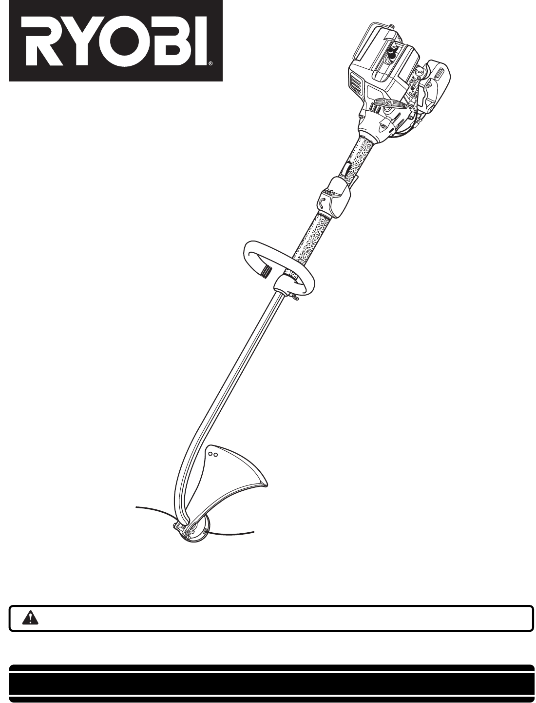
OPERATOR'S MANUAL
String Trimmer
PLT3043A
RY70101
Your new trimmer has been engineered and manufactured to Ryobi’s high standard for dependability, ease of operation, and operator
safety. Properly cared for, it will give you years of rugged, trouble-free performance.
Thank you for buying a Ryobi trimmer.
SAVE THIS MANUAL FOR FUTURE REFERENCE
WARNING: To reduce the risk of injury, the user must read and understand the operator’s manual.
- OPERATOR'S MANUAL 1
- String Trimmer 1
- PLT3043A 1
- TABLE OF CONTENTS 2
- TECHNICAL DATA 5
- FEATURES 6
- UNPACKING 6
- ASSEMBLY 7
- OPERATION 10
- MAINTENANCE 11
- TROUBLESHOOTING 14
- WARRANTY 16
- SAFETY DIRECTIVE 16
Résumé du contenu
Page 1 - PLT3043A
OPERATOR'S MANUALString TrimmerPLT3043ARY70101Your new trimmer has been engineered and manufactured to Ryobi’s high standard for dependability, e
Page 2 - TABLE OF CONTENTS
10TO START A COLD ENGINE:1. Lay trimmer on a flat, bare surface. Move switch to “I”(RUN) position.NOTE: Unit is equipped with a positive on-off swi
Page 3
11MAINTENANCE WARNING:Use only original manufacturer's replacement parts,accessories and attachments. Failure to do so cancause possible injury,
Page 4
12STRING REPLACEMENTSee Figures 12, 13, 14 and 15.1. Stop the engine, disconnect the spark plug wire. Holdthe string head and unscrew the spool retain
Page 5 - TECHNICAL DATA
13The fuel cap contains a non-serviceable filter and a checkvalve. A clogged fuel filter will cause poor engine perfor-mance. If performance improves
Page 6 - UNPACKING
14PROBLEMPROBLEMPROBLEMPROBLEMPROBLEMPOSPOSPOSPOSPOSSIBLE CASIBLE CASIBLE CASIBLE CASIBLE CAUSEUSEUSEUSEUSESOLUTIONSOLUTIONSOLUTIONSOLUTIONSOLUTIONIF
Page 7 - ASSEMBLY
15PROBLEMPROBLEMPROBLEMPROBLEMPROBLEMPOSPOSPOSPOSPOSSIBLE CASIBLE CASIBLE CASIBLE CASIBLE CAUSEUSEUSEUSEUSESOLUTIONSOLUTIONSOLUTIONSOLUTIONSOLUTIONIF
Page 8
16SOUND POWER/PRESSURE & HANDLE VIBRATION CHART FOR STRING TRIMMERS /BRUSHCUTTERSInformation on Noise Emission per European Machine Safety Directi
Page 9
17NOTES
Page 10 - OPERATION
983000-2001-03OPERATOR'S MANUALString TrimmerPLT3043ARY70101Ryobi Technologies GmbHItterpark 7D-40724 HildenGermanyTel.: +49 (0)2103 / 29 58 0Fax
Page 11 - MAINTENANCE
2TABLE OF CONTENTSSAFETY WARNING:Do not attempt to operate this trimmer until you have read thoroughly and understand completely all instructions,saf
Page 12
3SAFETY Secure long hair so it is above shoulder level to prevententanglement in any moving parts. Keep all bystanders, children, and pets a
Page 13
4SYMBOLSImportant: Some of the following symbols may be used on your tool. Please study them and learn their meaning. Properinterpretation of these sy
Page 14 - TROUBLESHOOTING
5SYMBOLSThe purpose of safety symbols is to attract your attention to possible dangers. The safety symbols, and the explanationswith them, deserve you
Page 15
6FEATURESFig. 1THROTTLE TRIGGERMUFFLERGUARDSTARTER GRIPCHOKE LEVERTHROTTLE CONTROLAND REAR HANDLEFRONT HANDLEDRIVE SHAFTHOUSINGSTRING HEADGRASS DEFLEC
Page 16 - SAFETY DIRECTIVE
7ASSEMBLYMUFFLER GUARD ASSEMBLYSee Figure 4.1. Remove muffler guard and two screws from the owner'skit.2. Attach the muffler guard to the rear ho
Page 17
8FILLING THE TANK1. Clean surface around fuel cap to prevent contamination.2. Loosen fuel cap slowly to release pressure and to keepfuel from escaping
Page 18
9OPERATIONADVANCING THE STRINGADVANCING STRING USING THE EZ LINE™ TAPADVANCE SYSTEMString advance is controlled by tapping string head on grasswhile r
Produits connexes et manuels pour Matériel de jardinage Ryobi PLT3043A
 (18 pages)
 (56 pages)
© 2020, manymanuals.fr. Tous droits réservés | 0.267 s |
 Manymanuals.com
 Manymanuals.de
 Manymanuals.fr
 Manymanuals.it
 Manymanuals.pl
 Manymanuals.cz
 Manymanuals.es
 Manymanuals-pt.com
Commentaires sur ces manuels