Page 12
OPERATION
WARNING:
The engine of your saw should never be running
when you are installing or removing blades. Stop the
engine and let it cool to prevent accidental contact
with the blade, muffler, etc. that could cause serious
injury. Disconnect the spark plug to make sure the
saw will not start.
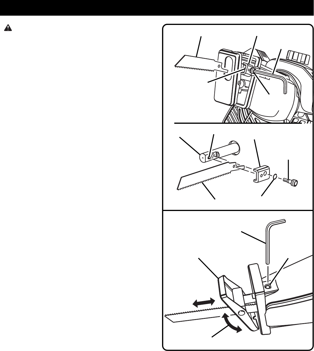
TO INSTALL BLADES
See Figure 5.
■ Use the 4 mm hex key provided with this saw.
■ Loosen the blade clamp screw enough to permit the saw
blade to be inserted over the pin between blade clamp
and saw bar.
NOTE: It is not necessary to remove the blade clamp from
the tool or the blade clamp screw from the blade clamp to
change the blade.
■ Align and place the hole in the shank of the blade on the
pin in the saw bar.
■ Tighten blade clamp screw securely. Do not overtighten
screw or use an aid with hex key.
■ Remove hex key. Put it in a safe place for future use, such
as a tool box.
NOTE: There may be times when the blade clamp sticks to
the saw bar and will not loosen enough to allow blades to be
installed or removed. If this happens, loosen the blade clamp
screw with the hex key, then tap lightly on the end of the hex
key with a mallet.
See Figure 5.
BASE (SHOE) ASSEMBLY
See Figure 6.
The base assembly of your reciprocating saw pivots up and
down approximately 15° in both directions. It also is adjustable,
allowing the use of the blade teeth at different positions on
the blade.
TO CHANGE POSITIONS OF THE BASE ASSEMBLY:
■ Loosen the set screw on bottom of the gear frame with the
4 mm hex key provided with this saw.
■ Reposition base assembly to desired position.
■ Retighten set screw securely. Do not overtighten screw
or use an aid with hex key.
■ Remove hex key and store it in a tool box or other safe
place for future use.
4 MM
HEX KEY
BLADE
PIN
PIN
BLADE CLAMP
BLADE CLAMP
SCREW
LOCK
WASHER
BLADE
SAW BAR
BLADE
CLAMP SCREW
BLADE CLAMP
Fig. 5
Fig. 6
15° PIVOT
BASE (SHOE)
ASSEMBLY
SET
SCREW
4 MM
HEX KEY
 (18 pages)
 (34 pages)
 (1 pages)
 Manymanuals.com
 Manymanuals.de
 Manymanuals.fr
 Manymanuals.it
 Manymanuals.pl
 Manymanuals.cz
 Manymanuals.es
 Manymanuals-pt.com
Commentaires sur ces manuels