Ryobi ts1341 Manuel d'utilisateur
Naviguer en ligne ou télécharger Manuel d'utilisateur pour Scies à onglets Ryobi ts1341. Ryobi TS1341 User's Manual Manuel d'utilisatio
- Page / 30
- Table des matières
- MARQUE LIVRES
Résumé du contenu
SAVE THIS MANUAL FOR FUTURE REFERENCEYour miter saw has been engineered and manufactured to Ryobi’s high standard for dependability, ease of operation
10FEATURESPRODUCT SPECIFICATIONSBlade Arbor ... 5/8 in.Blade Diameter...
11FEATURESKNOW YOUR COMPOUND MITER SAWSee Figure 1.Before attempting to use this product, familiarize yourself with all operating features and safety
12FEATURESPOSITIVE STOPS ON MITER TABLEPositive stops have been provided at 0°, 15°, 22-1/2°, 30°, and 45°. The 22-1/2° and 45° positive stops have be
13LOOSE PARTSWARNING:The use of attachments or accessories not listed might be hazardous and could cause serious personal injury.The following items a
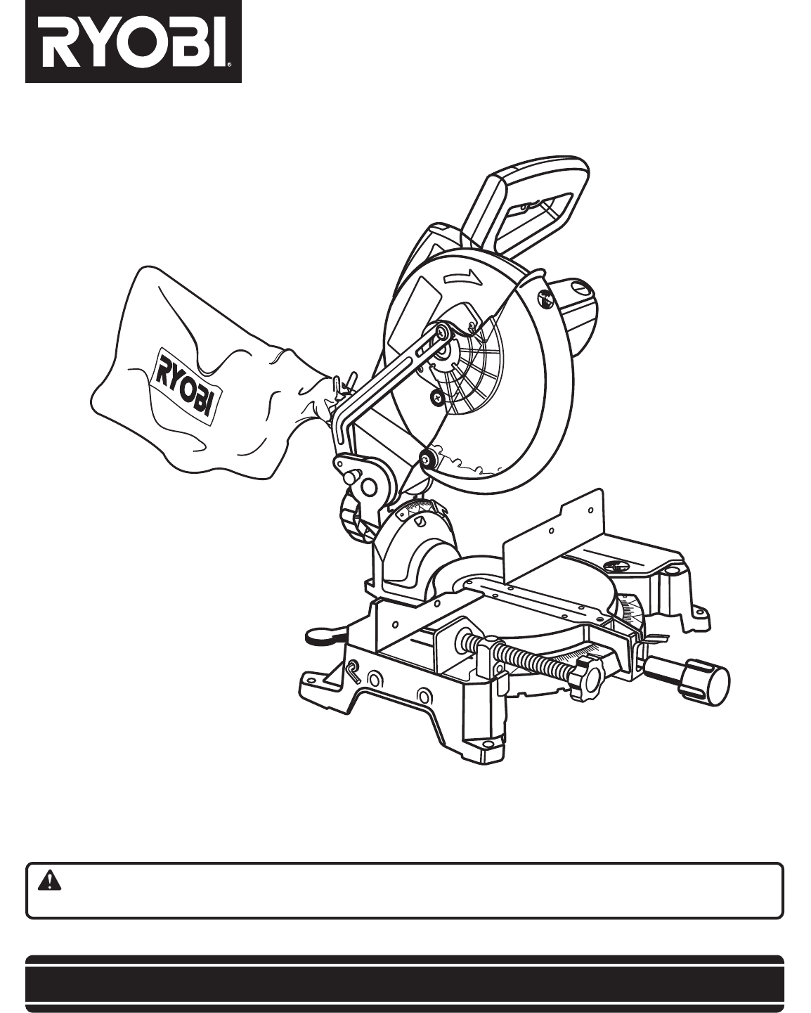
14ASSEMBLYUNPACKINGThis product requires assembly.n Carefully lift saw from the carton by the carrying handle and the saw base, and place it on a lev
15ASSEMBLYFig. 8Fig. 10TOLOOSENMITERLOCK HANDLETOTIGHTENDUST BAGEXHAUST PORTBASEWORK CLAMPFig. 9MITER LOCK HANDLESee Figure 8.To install the miter loc
16ASSEMBLYTO INSTALL / REPLACE THE BLADESee Figures 11 - 12.WARNING:A 10 in. blade is the maximum blade capacity of the saw. Never use a blade that is
17ASSEMBLYFig. 13WARNING:Make sure the spindle lock button is not engaged before reconnecting saw into power source. Never engage spindl
18ASSEMBLYSQUARING THE SAW BLADE TO THE FENCESee Figures 16 - 20n Unplug the saw.n Pull the saw arm all the way down and engage the lock pin to hold
19ASSEMBLYFig. 20SQUARING THE BLADE TO THE MITER TABLESee Figures 21 - 23.n Unplug the saw.n Pull the saw arm all the way down and engage the lock p
2n Introduction ...
20OPERATIONWARNING:Do not allow familiarity with tools to make you care-less. Remember that a careless fraction of a second issufficient to i
21Fig. 25OPERATIONn Tighten the miter lock handle securely.n Place the workpiece flat on the miter table with one edge securely against the fence. I
22OPERATIONn Grasp the stock firmly with one hand and secure it against the fence. Use the optional work clamp or a C-clamp to secure the workpiece w
23OPERATIONn Grasp the stock firmly with one hand and secure it against the fence. Use the optional work clamp or a C-clamp to secure the workpiece w
24OPERATION4 PITCH OF SIDENUMBER OF SIDES0°6M- 45.00°B- 0.00°5°10°15°20°25°30°35°40°45°50°55°60°65°70°75°80°85°90°578 910M- 36.00°B- 0.00°M- 3
25OPERATIONWhen setting the bevel and miter angles for compound miters, remember that the settings are interdependent; changing one angle changes th
26OPERATIONWARNING: To avoid a kickback and to avoid serious personal injury, never position the concave edge of bowed or warped material against the
27ADJUSTMENTSWARNING:Before performing any adjustment, make sure the tool is unplugged from the power suppl. Failure to heed this warning could result
28MAINTENANCEWARNING:When servicing, use only identical Ryobi replacement parts. Use of any other parts may create a hazard or cause p
29NOTES
3GENERAL SAFETY RULESWARNING: Read and understand all instructions. Failure to follow all instructions listed below, may result in electric shock, fir
RYOBI TECHNOLOGIES, INC.1428 Pearman Dairy Road, Anderson, SC 29625Post Office Box 1207, Anderson, SC 29622-1207Phone 1-800-525-2579www.ryobitools.com
4GENERAL SAFETY RULESn INSPECT TOOL CORDS PERIODICALLY. If damaged, have repaired by a qualified service technician atan authorized service facil
5n NEVER reach behind, under, or within three inches of the blade and its cutting path with your hands and fingers for any reason.n NEVER reach to p
6SYMBOLSSome of the following symbols may be used on this tool. Please study them and learn their meaning. Proper interpreta-tion of these symbols wil
7SYMBOLSSERVICEServicing requires extreme care and knowledge and should be performed only by a qualified service technician. For service we su
8EXTENSION CORDSWhen using a power tool at a considerable distance from a power source, be sure to use an extension cord that has the capacity to h
9GLOSSARY OF TERMSNon-Through CutsAny cutting operation where the blade does not extend completely through the thickness of the workpiece.Push
Produits connexes et manuels pour Scies à onglets Ryobi ts1341
 (30 pages)
 (104 pages)
© 2020, manymanuals.fr. Tous droits réservés | 0.239 s |
 Manymanuals.com
 Manymanuals.de
 Manymanuals.fr
 Manymanuals.it
 Manymanuals.pl
 Manymanuals.cz
 Manymanuals.es
 Manymanuals-pt.com
Commentaires sur ces manuels