Ryobi TS1351 Manuel de l'opérateur
Naviguer en ligne ou télécharger Manuel de l'opérateur pour Scies à onglets Ryobi TS1351. Ryobi TS1351 Operator`s manual Manuel d'utilisatio
- Page / 28
- Table des matières
- MARQUE LIVRES
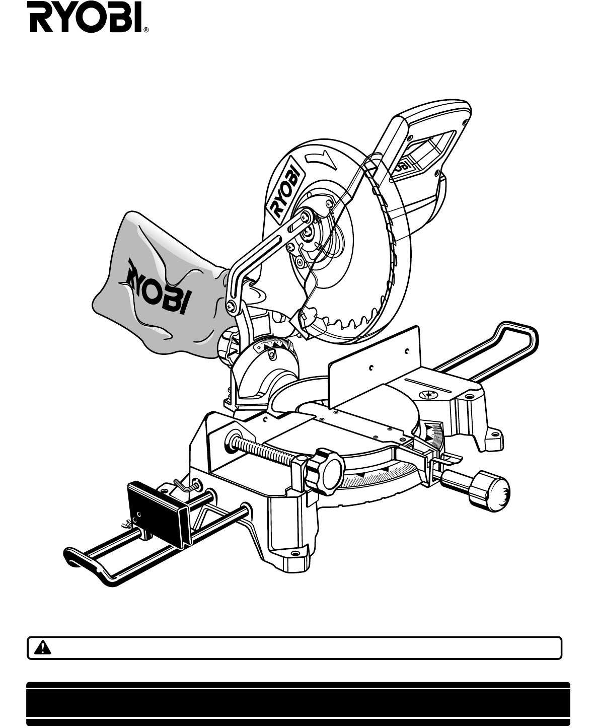
- OPERATOR'S MANUAL 1
- Model TS1351 1
- READ ALL INSTRUCTIONS 4
- RULES FOR SAFE OPERATION 4
- SAVE THESE INSTRUCTIONS 6
- UNPACKING 7
- See Figure 1 7
- TOOLS NEEDED 7
- LOOSE PARTS LIST 8
- BLADE WRENCH / STORAGE AREA 10
- CARRYING HANDLE 10
- MITER LOCK HANDLE 10
- SPINDLE LOCK BUTTON 10
- TRIGGER LOCK 10
- WARNING: 11
- CAUTION: 15
- ADJUSTMENTS 17
- See Figure 20 17
- See Figure 24 17
- See Figures 36 and 37 23
- See Figure 34 23
- See Figure 32 23
- See Figures 32 and 33 23
- CUTTING COMPOUND MITERS 24
- OPERATION 24
- CUTTING CROWN MOLDING 25
- See Figure 35 25
- LUBRICATION 27
- EXTENSION CORDS 27
Résumé du contenu
OPERATOR'S MANUAL10 in. (254 mm) Compound Miter SawModel TS1351 - Double InsulatedYour new Miter Saw has been engineered and manufactured to Ryob
Page 101.15304522.531.62304531.62FEATURESBLADE WRENCH / STORAGE AREASee Figure 2.A blade wrench is packed with your saw. One end of thewrench is a ph
Page 11022.531.622.531.6454530513015FEATURESPOSITIVE STOPS ON MITER TABLEPositive stops have been provided at 0°, 15°, 22-1/2°, 30°, and45°. The 22-1
Page 12115304533045.531.62153022.531.6245515304533.915304533.91.15304522.531.62304531.62ASSEMBLYWARNING:To prevent accidental starting that could cau
Page 13115304533.93045.531.62153022.531.624501515304533.93045.531.62153022.531.623031.6245TABLE EXTENSIONSSee Figures 11, 12, and 13.If you plan to u
Page 14ASSEMBLYTO INSTALL BLADESee Figures 15 and 16.WARNING:A 10 in. (254 mm) blade is the maximum blade capacityof your saw. Never use a blade that
Page 15ASSEMBLYCAUTION:Always install the blade with the blade teeth and thearrow printed on the side of the blade pointing down at thefront of the s
Page 16022.531.622.531.6454530513015ADJUSTMENTSWARNING:Failure to unplug your saw could result in accidentalstarting causing possible serious persona
Page 17022.531.622.531.645453051301545301515304531.6222.531.6222.545045301515304531.6222.531.6222.545045301515304531.6222.531.6222.5450ADJUSTMENTS T
Page 1845301515304531.6222.531.6222.545045301515304531.6222.531.6222.545045301515304531.6222.531.6222.5450ADJUSTMENTSSQUARING THE BLADE TO THE MITER
Page 19ADJUSTMENTSBEVEL PIVOT ADJUSTMENT Your compound miter saw should bevel easily by loos-ening the bevel lock knob and tilting the saw arm to th
Page 2TABLE OF CONTENTSPRODUCT SPECIFICATIONSBlade Arbor 5/8 in. (16 mm)Blade Diameter 10 in. (254 mm)Rating 120 volts, 60Hz, AC OnlyNo Load Speed 50
Page 20115304533.93045.531.62153022.531.6245CUTTING WITH YOUR COMPOUNDMITER SAWWARNING:When using a work clamp or C-clamp to secure yourworkpiece, cl
Page 21115304533.93045.531.62153022.531.6245015045BEVELSCALEINDICATORSCREWSCALEINDICATOROPERATION Pull out the lock pin and lift saw arm to its full
Page 22031522.5015304522.531.62OPERATION Grasp the stock firmly with one hand and secure it againstthe fence. Use the optional work clamp or a C-cla
Page 23 Recheck miter angle setting. Make a test cut in scrapmaterial. Place the workpiece flat on the miter table with one edgesecurely against th
Page 24CUTTING COMPOUND MITERSTo aid in making the correct settings, the compound angle setting chart below has been provided. Since compound cutsare
Page 25When setting the bevel and miter angles for compoundmiters, remember that the settings are interdependent; chang-ing one angle changes the oth
Page 26022.531.622.531.6454530513015115304533.93045.531.62153022.531.624534531.624 55331.631.64 55331.645WRONGWARNING:To avoid a kickback and to avoi
Page 27WARNING:When servicing, use only identical Ryobi replacementparts. Use of any other part may create a hazard or causeproduct damage.GENERALAvo
Page 28972000-956 09-02RYOBI TECHNOLOGIES, INC.1428 Pearman Dairy Road Anderson SC 29625Post Office Box 1207 Anderson SC 29622-1207Phone 1-800-52
Page 3RULES FOR SAFE OPERATIONThe purpose of safety symbols is to attract your attention to possible dangers. The safety symbols, and the explanation
Page 4Safe operation of this power tool requires that you read andunderstand this operator's manual and all labels affixed tothe tool. Safety is
Page 5 NEVER reach behind, under, or within three inches of theblade and its cutting path with your hands and fingers forany reason. NEVER hand hol
Page 6SAVE THESE INSTRUCTIONSRULES FOR SAFE OPERATION STAY ALERT AND EXERCISE CONTROL. Watch whatyou are doing and use common sense. Do not operatet
Page 7UNPACKING Lift the saw arm by the handle. Hand pressure shouldremain on the saw arm to prevent sudden rise uponrelease of the tie wrap. Exami
Page 8The following items are included with your Compound Miter Saw: 10 in. (254 mm) Saw Blade Miter Lock Handle Dust Bag Dust Guide Stop Block
Page 9FEATURESKNOW YOUR COMPOUND MITER SAWSee Figure 2.Before attempting to use your saw, familiarize yourself withall operating Features and Rules f
Produits connexes et manuels pour Scies à onglets Ryobi TS1351

 (104 pages)
© 2020, manymanuals.fr. Tous droits réservés | 1.480 s |
 Manymanuals.com
 Manymanuals.de
 Manymanuals.fr
 Manymanuals.it
 Manymanuals.pl
 Manymanuals.cz
 Manymanuals.es
 Manymanuals-pt.com
Commentaires sur ces manuels