Ryobi TS1553 Manuel d'utilisateur
Naviguer en ligne ou télécharger Manuel d'utilisateur pour Scies à moteur Ryobi TS1553. Ryobi TS1553 User Manual Manuel d'utilisatio
- Page / 28
- Table des matières
- MARQUE LIVRES
- OPERATOR’S MANUAL 1
- TABLE OF CONTENTS 2
- INTRODUCTION 2
- WARRANTY 2
- GENERAL SAFETY RULES 3
- SPECIFIC SAFETY RULES 4
- WARNING: 6
- ELECTRICAL 7
- GLOSSARY OF TERMS 8
- FEATURES 10
- TOOLS NEEDED 11
- LOOSE PARTS LIST 12
- ASSEMBLY 13
- OPERATION 19
- ADJUSTMENTS 26
- MAINTENANCE 27
Résumé du contenu
SAVE THIS MANUAL FOR FUTURE REFERENCEYour miter saw has been engineered and manufactured to our high standard for dependability, ease of operation,
10FEATURESFig. 3KNOW YOUR COMPOUND MITER SAWSee Figure 1.The safe use of this product requires an understanding of the information on the tool and in
11FEATURESPOSITIVE STOPS ON MITER TABLEPositive stops have been provided at 0°, 15°, 22-1/2°, 31.62°, and 45°. The 0°, 15°, 22-1/2°, 31.62°, and 45° p
12LOOSE PARTS LISTFig. 6WARNING:The use of attachments or accessories not listed might be hazardous and could cause serious personal injury.The follow
13ASSEMBLYtrace hoLes at these Locations For hoLe patternWARNING:Do not attempt to modify this tool or create accessories not recommended for use wit
14Miter Lock handLeMiter tabLeASSEMBLYMITER LOCK HANDLESee Figure 8.To install the miter lock handle, place the threaded stud on the end of the miter
15ASSEMBLYTO INSTALL / REPLACE THE BLADESee Figures 11 - 12.WARNING:A 12 in. blade is the maximum blade capacity of the saw. Never use a blade that is
16ASSEMBLYFig. 13view oF Miter tabLe sQuare with Fence Miter Lock pLateMiter Lock handLeMiter tabLethroat pLateFraMing sQuareNOTE: Many of the illustr
17ASSEMBLYSQUARING THE BLADE TO THE FENCESee Figures 17 - 19. Unplug the saw. Pull the saw arm all the way down and engage the lock pin to hold th
18ASSEMBLYscaLe indicatorMiter scaLeindicator screwbeveL scaLeSQUARING THE BLADE TO THE MITER TABLESee Figures 20 - 23. Unplug the saw. Pull the s
19OPERATIONWARNING:Do not allow familiarity with tools to make you care-less. Remember that a careless fraction of a second is sufficient to i
2 Introduction ...
20OPERATION Lift and hold the miter lock plate then rotate the miter table until the pointer aligns with zero on the miter scale. Release the mite
21OPERATION Loosen the bevel lock knob and move the saw arm to the left to the desired bevel angle. Bevel angles can be set from 0° to 45°. Ali
22OPERATION Place the workpiece flat on the miter table with one edge securely against the fence. If the board is warped, place the convex side again
23OPERATION4 PITCH OF SIDENUMBER OF SIDES0°6M- 45.00°B- 0.00°5°10°15°20°25°30°35°40°45°50°55°60°65°70°75°80°85°90°578 910M- 36.00°B- 0.00°M- 3
24OPERATIONWhen setting the bevel and miter angles for compound miters, remember that the settings are interdependent; changing one angle changes t
25OPERATIONwrongWARNING: To avoid a kickback and to avoid serious personal injury, never position the concave edge of bowed or warped material agains
26ADJUSTMENTSWARNING:Before performing any adjustment, make sure the tool is unplugged from the power supply. Failure to heed this warning could resul
27MAINTENANCEWARNING:When servicing, use only identical replacement parts. Use of any other parts may create a hazard or cause product
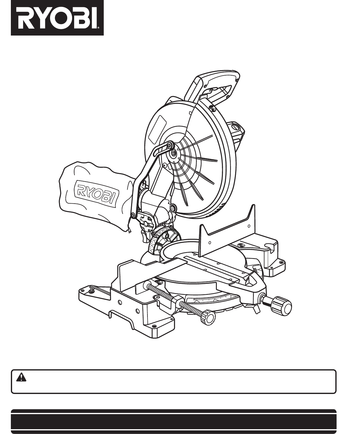
983000-9417-16-09 (REV:01)TS1553OPERATOR’S MANUAL10 in. Compound Miter SawTS1553 - Double Insulated• SERVICENow that you have purchased your tool, sh
3GENERAL SAFETY RULESWARNING: Read and understand all instructions. Failure to follow all instructions listed below, may result in electric shock, fire
4GENERAL SAFETY RULES NEVER USE IN AN EXPLOSIVE ATMOSPHERE. Normal sparking of the motor could ignite fumes. INSPECT TOOL CORDS PERIODICAL
5SPECIFIC SAFETY RULES NEVER hand hold a workpiece that is too small to be clamped. Keep hands clear of the cutting area. NEVER reach behind, un
6SYMBOLSSome of the following symbols may be used on this tool. Please study them and learn their meaning. Proper interpretation of
7ELECTRICALDOUBLE INSULATIONDouble insulation is a concept in safety in electric power tools, which eliminates the need for the usual three-wire groun
8GLOSSARY OF TERMSNon-Through CutsAny cutting operation where the blade does not extend completely through the thickness of the workpiece.Push
9FEATURESFig. 1PRODUCT SPECIFICATIONSArbor .................. 5/8 in.Blade Inner Washer ...
Plus de documents pour Scies à moteur Ryobi TS1553


Produits connexes et manuels pour Scies à moteur Ryobi TS1553
 (28 pages)
 (28 pages)
 (34 pages)
© 2020, manymanuals.fr. Tous droits réservés | 1.026 s |
 Manymanuals.com
 Manymanuals.de
 Manymanuals.fr
 Manymanuals.it
 Manymanuals.pl
 Manymanuals.cz
 Manymanuals.es
 Manymanuals-pt.com
Commentaires sur ces manuels