Ryobi TSS101L Manuel d'utilisateur
Naviguer en ligne ou télécharger Manuel d'utilisateur pour Scies à moteur Ryobi TSS101L. Ryobi TSS101L User Manual Manuel d'utilisatio
- Page / 34
- Table des matières
- MARQUE LIVRES
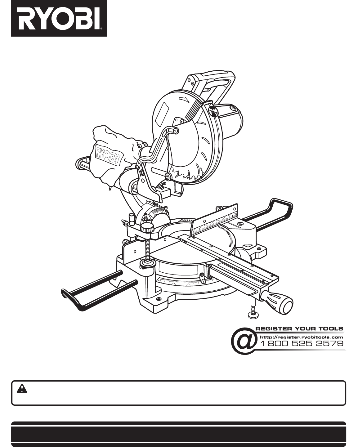
- OPERATOR’S MANUAL 1
- TABLE OF CONTENTS 2
- INTRODUCTION 2
- WARRANTY 2
- GENERAL SAFETY RULES 3
- SPECIFIC SAFETY RULES 4
- WARNING: 6
- CAUTION: 6
- ELECTRICAL 7
- GLOSSARY OF TERMS 8
- FEATURES 10
- TOOLS NEEDED 11
- LOOSE PARTS LIST 12
- ASSEMBLY 13
- OPERATION 21
- ADJUSTMENTS 31
- MAINTENANCE 33
Résumé du contenu
SAVE THIS MANUAL FOR FUTURE REFERENCEYour miter saw has been engineered and manufactured to our high standard for dependability, ease of operation, an
10FEATURESKNOW YOUR COMPOUND MITER SAWSee Figure 2.The safe use of this product requires an understanding of the information on the tool and in this o
11FEATURESThe following tools (not included) are needed for making adjustments or installing the blade:TOOLS NEEDEDFig. 6COMBINATION SQUAREFRAMING SQU
12LOOSE PARTS LISTFig. 7WARNING:The use of attachments or accessories not listed might be hazardous and could cause serious personal injury. Blade W
13ASSEMBLYTRACE HOLES AT THESE LOCATIONS FOR HOLE PATTERNWARNING:Do not attempt to modify this product or create accessories not recommended for use
14ASSEMBLYThe compound miter saw should be mounted to a firm supporting surface such as a workbench. Four bolt holes have been provided in the saw ba
15ASSEMBLYWORK CLAMP See Figure 11.WARNING:In some operations, the work clamp assembly may interfere with the operation of the blade guard assembly.
16ASSEMBLYTO INSTALL / REPLACE THE BLADESee Figures 14 - 15.WARNING:A 10 in. blade is the maximum blade capacity of the saw. Never use a blade that is
17ASSEMBLYWARNING:Make sure the spindle lock button is not engaged before reconnecting saw into power source. Never engage spindle lock button when
18ASSEMBLYREMOVING / REPLACING THE THROAT PLATESee Figure 17.WARNING:The throat plate must be below the saw table. If the throat plate is too high or
19ASSEMBLYSQUARING THE BLADE TO THE FENCESee Figures 18 - 21. Unplug the saw. Pull the saw arm all the way down and engage the lock pin to hold th
2 Introduction ...
20MITER TABLECOMBINATION SQUAREBLADEMITER FENCEASSEMBLYSCALE INDICATORFig. 22INDICATOR SCREWBEVEL SCALESQUARING THE BLADE TO THE MITER TABLESee Figure
21OPERATIONWARNING:Do not allow familiarity with tools to make you care-less. Remember that a careless fraction of a second is sufficient to inflict s
22OPERATIONTO MAKE NON-SLIDING CUTSWARNING:Securely tighten the slide lock knob when making any non-sliding cuts. Failure to tighten the knob could re
23Fig. 28INDICATOR POINTOPERATIONTO BEVEL CUTSee Figures 28 - 29.A bevel cut is made by cutting across the grain of the workpiece with the blade angle
24OPERATIONTO COMPOUND MITER CUTSee Figures 30 - 31.A compound miter cut is a cut made using a miter angle and a bevel angle at the same time. This ty
2500OPERATIONTO SUPPORT LONG WORKPIECESSee Figure 32.Long workpieces need extra supports. Supports should be placed along the workpiece so it does not
26OPERATIONWARNING:Never make a cut by pulling the saw toward you as the blade can climb on top of the workpiece and come toward you. Failure to heed
27OPERATIONMAKING AN AUXILIARY FENCESee Figure 35.Certain unusual cuts may benefit from a thicker miter fence (auxiliary fence) due to the size and po
28OPERATION4 PITCH OF SIDENUMBER OF SIDES0°6M- 45.00°B- 0.00°5°10°15°20°25°30°35°40°45°50°55°60°65°70°75°80°85°90°578 910M- 36.00°B- 0.00°M-
29OPERATIONFig. 36When cutting crown molding by this method, the bevel angle should be set at 33.85°. The miter angle should be set at 31.6° either ri
3GENERAL SAFETY RULESWARNING: Read and understand all instructions. Failure to follow all instructions listed below, may result in electric shock, fir
30OPERATIONWRONGWARNING: To avoid a kickback and to avoid serious personal injury, never position the concave edge of bowed or warped material against
31ADJUSTMENTSWARNING:Before performing any adjustment, make sure the tool is unplugged from the power supply. Failure to heed this warning could resul
32ADJUSTMENTSTRAVEL PIVOT INSPECTION The saw arm should rise completely to the up position by itself. If the saw arm does not raise by itself or i
33MAINTENANCEWARNING:When servicing, use only identical replacement parts. Use of any other parts may create a hazard or cause product damage.WARNING:
ONE WORLD TECHNOLOGIES, INC.1428 Pearman Dairy Road, Anderson, SC 29625Phone 1-800-525-2579www.ryobitools.comWARNING:Some dust created by power sandin
4GENERAL SAFETY RULES NEVER USE IN AN EXPLOSIVE ATMOSPHERE. Normal sparking of the motor could ignite fumes. INSPECT TOOL CORDS PERIODICALLY. If
5 NEVER PERFORM ANY OPERATION FREEHAND. Always place the workpiece to be cut on the miter table and position it firmly against the fence as a backst
6SYMBOLSSome of the following symbols may be used on this tool. Please study them and learn their meaning. Proper interpretation of these symbols wil
7ELECTRICALSPEED AND WIRINGThe no-load speed of this tool is approximately 5,000 RPM. This speed is not constant and decreases under a load or with lo
8GLOSSARY OF TERMSPush Blocks (for jointer planers)Device used to feed the workpiece over the jointer planer cutterhead during any operation. This aid
9FEATURESFig. 2PRODUCT SPECIFICATIONSBlade Arbor ................ 5/8 in.Blade Diameter .....
Plus de documents pour Scies à moteur Ryobi TSS101L


Produits connexes et manuels pour Scies à moteur Ryobi TSS101L
 (34 pages)
 (36 pages)
 (32 pages)
© 2020, manymanuals.fr. Tous droits réservés | 0.116 s |
 Manymanuals.com
 Manymanuals.de
 Manymanuals.fr
 Manymanuals.it
 Manymanuals.pl
 Manymanuals.cz
 Manymanuals.es
 Manymanuals-pt.com
Commentaires sur ces manuels