Ryobi HP1442M Manuel d'utilisateur Page 1
Naviguer en ligne ou télécharger Manuel d'utilisateur pour Outils Ryobi HP1442M. Ryobi HP1442M User Manual Manuel d'utilisatio
- Page / 16
- Table des matières
- MARQUE LIVRES
Noté. / 5. Basé sur avis des utilisateurs
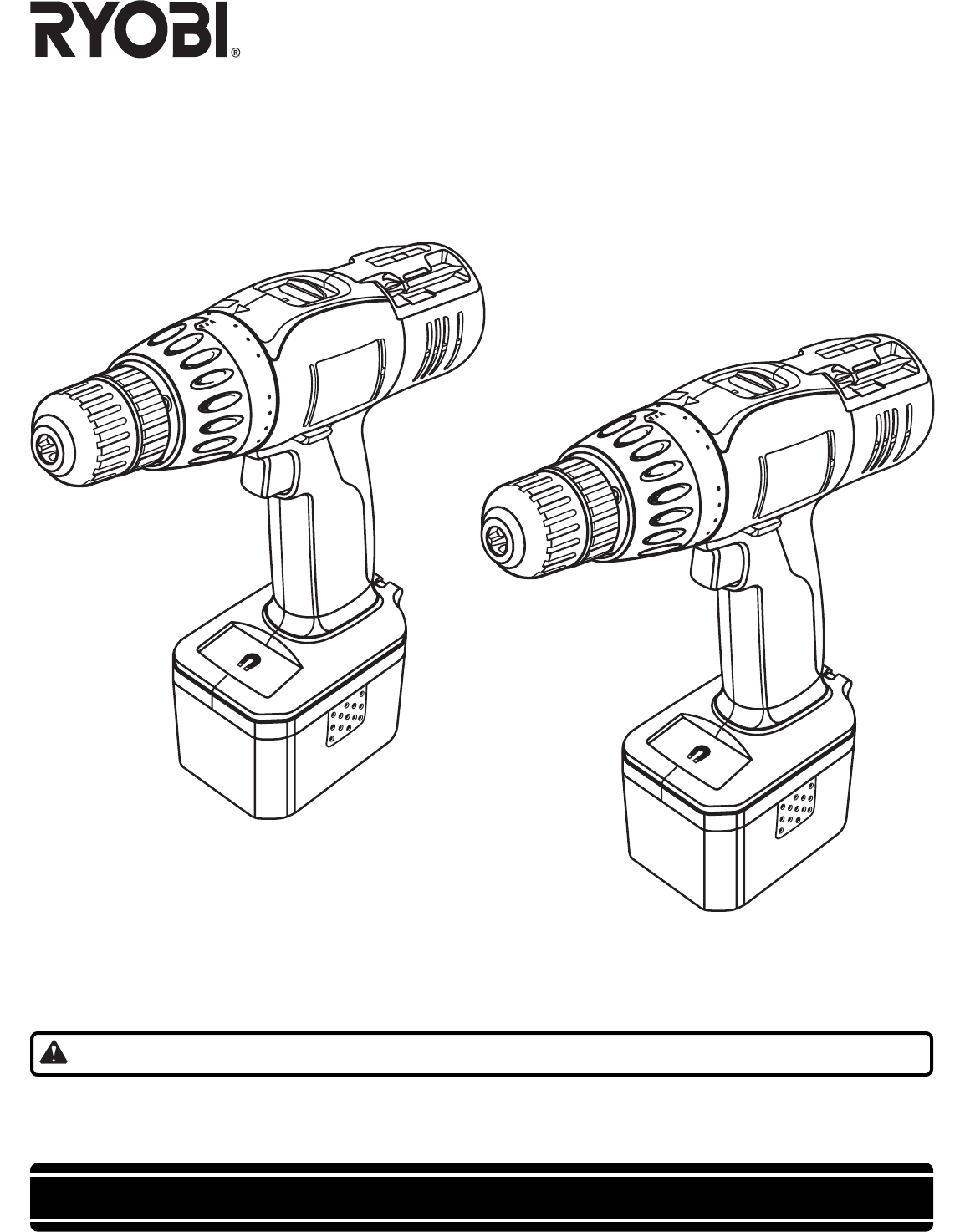
THANK YOU FOR BUYING A RYOBI CORDLESS DRILL-DRIVER.
Your new cordless drill-driver has been engineered and manufactured to Ryobi’s high standard for dependability, ease of
operation, and operator safety. Properly cared for, it will give you years of rugged, trouble-free performance.
CAUTION: Carefully read through this entire operator’s manual before using your new cordless drill-driver.
Pay close attention to the Rules for Safe Operation, Warnings, and Cautions. If you use your cordless drill-driver properly
and only for what it is intended, you will enjoy years of safe, reliable service.
Thank you again for buying Ryobi tools.
OPERATOR'S MANUAL
CORDLESS DRILL-DRIVER
MODEL NOS. HP1442M / HP1802M
SAVE THIS MANUAL FOR FUTURE REFERENCE
MODEL HP1442M
MODEL HP1802M
20
24
5
20
24
5
Résumé du contenu
Page 1 - MODEL NOS. HP1442M / HP1802M
THANK YOU FOR BUYING A RYOBI CORDLESS DRILL-DRIVER.Your new cordless drill-driver has been engineered and manufactured to Ryobi’s high standard for de
Page 2 - TABLE OF CONTENTS
Page 1020245OPERATIONKEYLESS CHUCKSee Figure 6.A keyless chuck has been provided with your drill to allow foreasy installation and removal of bits. As
Page 3
Page 1120245OPERATIONWRONGCHUCK JAWSDRILL BITCHUCK COLLARCHUCK BODYINSTALLING BITS Place the direction of rotation selector in center position.This w
Page 4 - WARNING:
Page 12202024520245OPERATIONSCREWDRIVINGTORQUE ADJUSTMENT(Driving power of your drill-driver)When using your drill-driver for various driving applicat
Page 5 - SAVE THESE INSTRUCTIONS
Page 13OPERATIONWARNING:Always wear safety goggles or safety glasses with sideshields when operating tool. Failure to do so could resultin objects bei
Page 6 - FEATURES
Page 142024520245OPERATIONCHUCK REMOVALSee Figures 15, 16, and 17. Lock the switch trigger by placing the direction of rotationselector in center pos
Page 7
Page 15MAINTENANCEWARNING:When servicing use only identical Ryobi replacementparts. Use of any other parts can create a hazard or causeproduct damage.
Page 8
OPERATOR'S MANUALCORDLESS DRILL-DRIVERMODEL NOS. HP1442M / HP1802MRYOBI TECHNOLOGIES, INC.1428 Pearman Dairy Road Anderson, SC 29625Post Office B
Page 9
Page 2 General Safety Rule ...
Page 10 - OPERATION
Page 3Tool Use and Care Use clamps or other practical way to secure andsupport the workpiece to a stable platform. Holdingthe work by hand or against
Page 11 - WARNING:
Page 4SPECIFIC SAFETY RULES AND/OR SYMBOLS WARNING:Some dust created by power sanding, sawing, grinding,drilling, and other construction activities co
Page 12 - LEVEL DRILLING
Page 5SYMBOLS SYMBOL NAME DESIGNATION/EXPLANATIONV Volts VoltageA Amperes CurrentHz Hertz Frequency (cycles per second)min Minutes TimeAlternating C
Page 13
Page 6FEATURESPRODUCT SPECIFICATIONS: DRILL-DRIVER HP1442M HP1802MChuck 3/8 in. Keyless 1/2 in. KeylessMotor DC Motor 14.4 Volt DC Motor 18 VoltGear T
Page 14
Page 720245FEATURESKEYLESSCHUCKBITSTORAGEAREATORQUEADJUSTMENTRINGSWITCHTRIGGERLEVELMODEL HP1442MMODEL HP1802MFig. 1Fig. 1aBATTERYPACKDIRECTION OFROTAT
Page 15 - MAINTENANCE
Page 8OPERATIONFig. 2WARNING:If any parts are missing, do not operate tool until themissing parts are replaced. Failure to do so could resultin possib
Page 16
Page 92024520245OPERATIONFig. 5Fig. 4SWITCHSee Figure 4.Your drill starts and stops by depressing and releasing theswitch trigger. Release the switch
Produits connexes et manuels pour Outils Ryobi HP1442M
Outils Ryobi HP1201 Manuel d'utilisateur
 (14 pages)
(14 pages)
Outils Ryobi P230 Manuel d'utilisateur
(16 pages)
(16 pages)
Outils Ryobi AG401 Manuel d'utilisateur
(14 pages)
(14 pages)
Outils Ryobi RY30931 Manuel d'utilisateur
(30 pages)
(30 pages)
Outils Ryobi DP120 Manuel d'utilisateur
(18 pages)
(18 pages)
Outils Ryobi RY1201 Manuel d'utilisateur
(14 pages)
(14 pages)
Outils Ryobi AP1300 Manuel d'utilisateur
(18 pages)
(18 pages)
Outils Ryobi HP512K Manuel d'utilisateur
(20 pages)
(20 pages)
Outils Ryobi SGL1150 Manuel d'utilisateur
(13 pages)
(13 pages)
Outils Ryobi TR45K Manuel d'utilisateur
(20 pages)
(20 pages)
Outils Ryobi AG452 Manuel d'utilisateur
(16 pages)
(16 pages)
Outils Ryobi AG451 Manuel d'utilisateur
(14 pages)
(14 pages)
Outils Ryobi P2005 Manuel d'utilisateur

 (34 pages)
(34 pages)
Outils Ryobi P2500 Manuel d'utilisateur
(16 pages)
(16 pages)
Outils Ryobi HP472 Manuel d'utilisateur
(20 pages)
(20 pages)
Outils Ryobi CDI-1803M Manuel d'utilisateur


 (50 pages)
(50 pages)
© 2020, manymanuals.fr. Tous droits réservés | 0.433 s |
 Manymanuals.com
 Manymanuals.de
 Manymanuals.fr
 Manymanuals.it
 Manymanuals.pl
 Manymanuals.cz
 Manymanuals.es
 Manymanuals-pt.com
Commentaires sur ces manuels