English – 19
ASSEMBLY
Assembly of the blade and trimmer
head
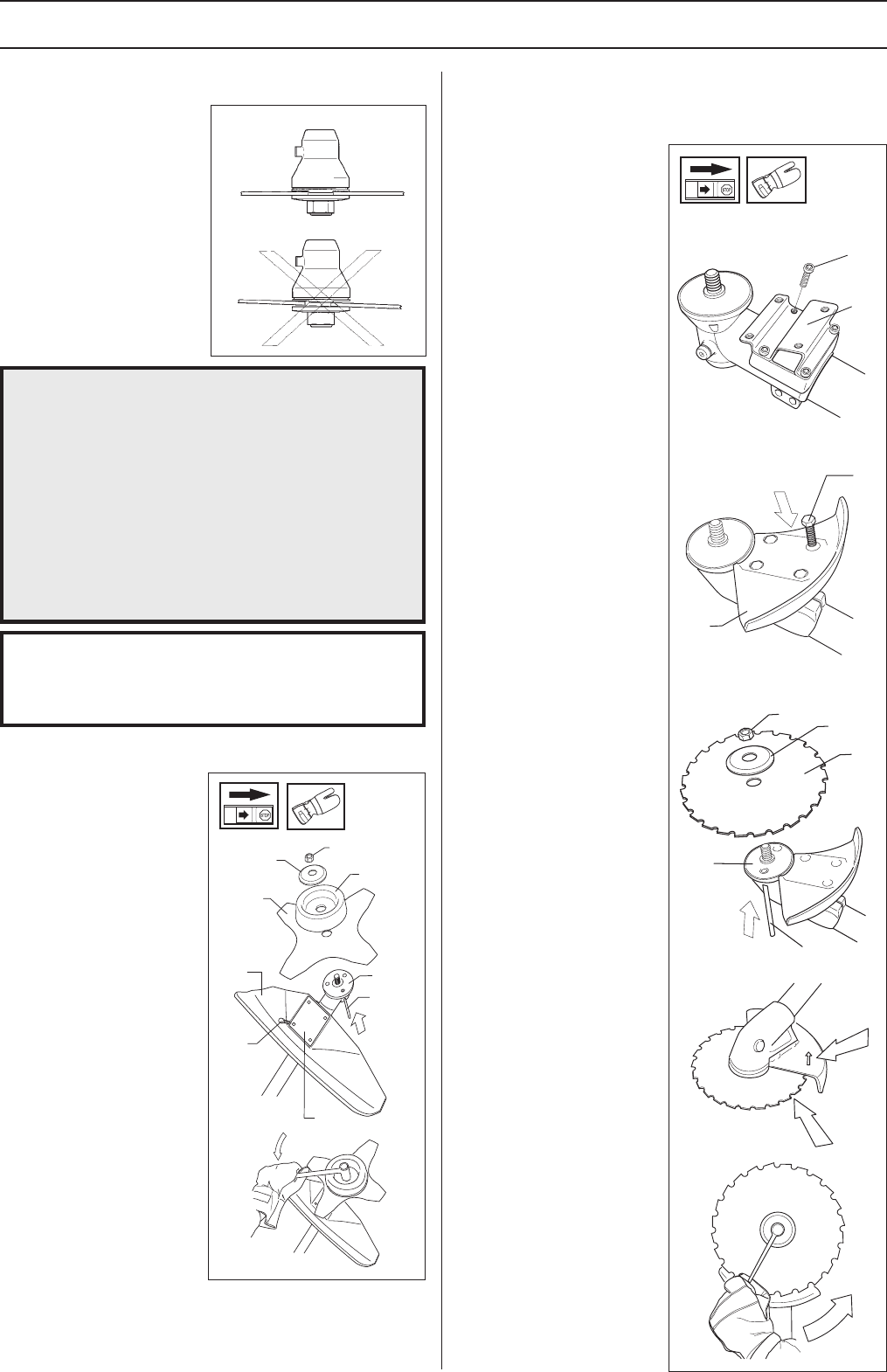
Assembling the blade guard and
clearing blade
•Fasten the bracket(H)
using the four screws (I).
• The guard (A) is fitted
using 4 screws (L) as set
out in the diagram.
NOTE! Use the
recommended blade
guard.
• Fit the drive disc (B) on
the output axle.
• Turn the blade axle until
one of the holes in the
drive disc aligns with the
hole in the gear housing.
• Insert the locking pin (C)
in the hole so that the
axle is locked.
• Place the blade (D) and
support flange (F) on the
output axle.
• Fit the nut (G). The
tightening torque of the
nut is 35-50 Nm (3.5 - 5
kpm). Use the socket
spanner in the tool kit.
Hold the handle of the
spanner as close to the
blade guard as possible.
The nut is tightened
when the spanner is
turned against the
direction of rotation (left-
hand thread).
• When slacking off and
tightening the saw blade
nut, the hands may be
injured by the blade
teeth. Always hold your
hand protected by the
blade guard. This is
facilitated by the use of a
long box spanner. The
illustration shows the area
in which you should keep
the box spanner.
It is extremely important that
the disc drive’s/support
flange’s guide engages
correctly in the cutting
equipment’s centre hole when
assembling the cutting
equipment. Cutting
equipment assembled
incorrectly can result in
serious and/or fatal personal
injury.
kpm). Use the socket spanner in the tool kit. Hold the
handle of the spanner as close to the blade guard as possible.
The nut is tightened when the spanner is turned against the
direction of rotation (left-hand thread).
• The guard (A) is fitted
using 4 screws (L) and the
support plate (M) as set
out in the diagram.
NOTE! Use the
recommended blade
guard.
• Fit the drive disc (B) on
the output axle.
• Turn the blade axle until
one of the holes in the
drive disc aligns with the
hole in the gear housing.
• Insert the locking pin (C)
in the hole so that the axle
is locked.
• Place the blade (D),
support cup (E) and
support flange (F) on the
output axle.
• Fit the nut (G). The
tightening torque of the
nut is 35-50 Nm (3,5 - 5
Assembling the blade guard and
grass blade
IMPORTANT INFORMATION
The machine must be equipped with the correct
handlebars, blade guard and harness if either a
clearing blade or grass blade are to be used.
WARNING!
Do not attach any blade to the unit
without proper installation of all required
parts. Failure to use the proper parts can
cause the blade to fly off and seriously
injure the operator and/or bystanders.
Under no circumstances may the cutting
equipment be used without an approved
guard fitted. See the chapter
“Technical
data”
. If the wrong guard or a defective
guard is fitted this can cause serious
personal injury.
!
G
F
E
D
B
C
A
L
M
G
F
D
B
C
L
A
 Manymanuals.com
 Manymanuals.de
 Manymanuals.fr
 Manymanuals.it
 Manymanuals.pl
 Manymanuals.cz
 Manymanuals.es
 Manymanuals-pt.com
Commentaires sur ces manuels