Ryobi BS902 Manuel d'utilisateur
Naviguer en ligne ou télécharger Manuel d'utilisateur pour Scies à moteur Ryobi BS902. Ryobi BS902 User Manual Manuel d'utilisatio
- Page / 26
- Table des matières
- DEPANNAGE
- MARQUE LIVRES
Résumé du contenu
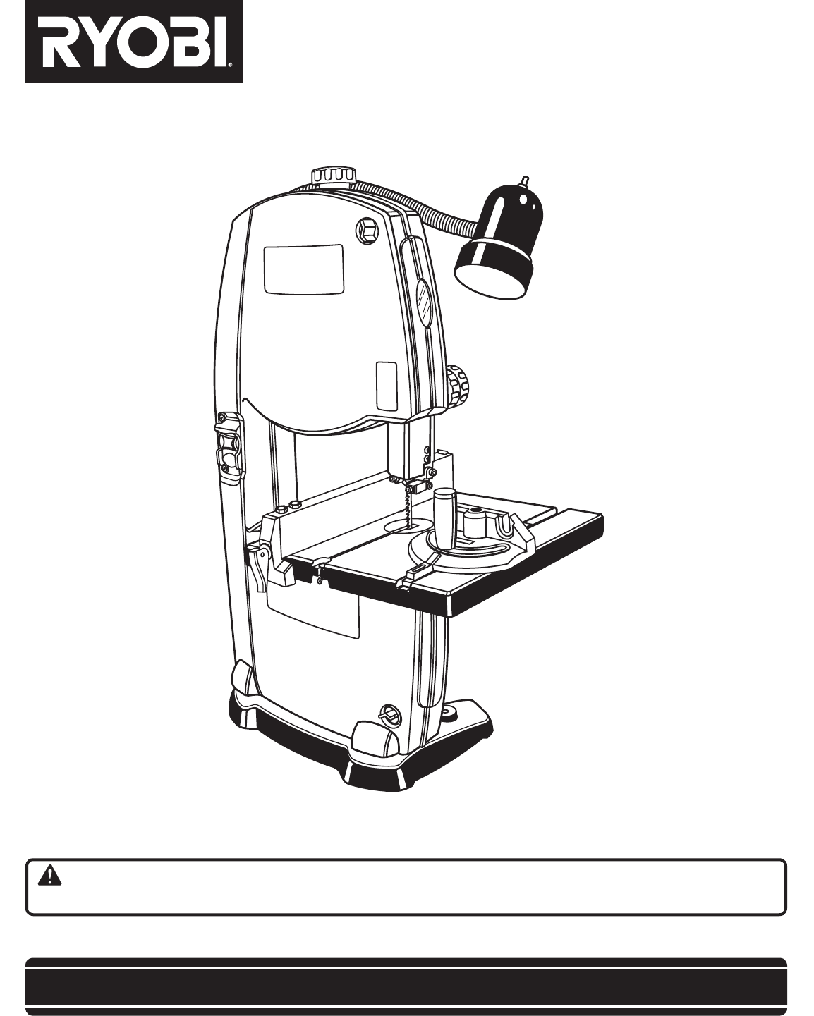
SAVE THIS MANUAL FOR FUTURE REFERENCEYour band saw has been engineered and manufactured to our high standard for dependability, ease of operation,
10FEATURESSAW BLADESaw comes with a standard 1/4 in. (6 mm) blade.SAW TABLE WITH THROAT PLATEYour band saw has a square 11-13/16 in. (30 cm) aluminum
11TOOLS NEEDEDThe following tools (not included) are needed for making adjustments or installing the blade:Fig. 5PHILLIPS SCREWDRIVERCOMBINATION SQUA
12ASSEMBLYHOLES IN SAW BASEFig. 5UNPACKINGThis product requires assembly. Carefully remove the tool and any accessories from the box. Place it on a
13ASSEMBLYgo through holes in the saw base and material the saw is being mounted to. If machine bolts are being used, make sure bolts are long enough
14ASSEMBLYSQUARING THE SAW TABLE TO THE BLADESee Figure 8. Turn the lock knob counterclockwise to unlock the blade guide assembly. Turning the blade
15ASSEMBLYTRACKING THE BLADESee Figure 10.NOTE: Adjust blade tension properly before making tracking adjustments. Check that the blade guides are not
16OPERATIONWARNING:Do not allow familiarity with tools to make you care-less. Remember that a careless fraction of a second is sufficient to
17OPERATIONSCROLL CUTTINGFor general type scroll cutting, follow the pattern lines by pushing and turning the workpiece at the same time. Do not try t
18OPERATIONTILTING THE TABLESee Figure 13. Loosen the table lock handle slightly. Turn the angle adjustment knob, tilting the saw table to
19ADJUSTMENTSINSTALLING AND ADJUSTING THE BLADESee Figures 16 and 17. Loosen and remove the wing nut and table aligning bolt from the saw table.
2 Introduction ...
20ADJUSTMENTSFig. 19ADJUSTING BLADE GUIDE ASSEMBLYSee Figures 18 and 19. WARNING:The blade guides have been preset at the factory. These setti
21ADJUSTMENTSADJUSTING THRUST BEARINGS, BLADE GUIDE SUPPORT, AND BLADE GUIDESSee Figures 20 - 22.The upper and lower blade guides and thrust
22MAINTENANCEADJUSTMENTSTo Adjust Blade Guides:The blade guides help keep the blade from twisting and binding. The blade will be ruined if th
23MAINTENANCELOWER WHEELPULLEY SHAFTMOTOR PULLEYFig. 25DRIVE BELTFig. 24LOWER WHEELBRUSHFig. 23TIRESCREW Remove the nut and washer from the middle o
24TROUBLESHOOTINGPROBLEM CAUSE SOLUTIONMotor will not run. 1. Problem with On-Off switch or 1. Have worn parts replaced before power cord
25NOTES
• SERVICENow that you have purchased your tool, should a need ever exist for repair parts or service, simply contact your nearest Authorized Service
3GENERAL SAFETY RULESWARNING: Read and understand all instructions. Failure to follow all instructions listed below, may result in electric shock, fir
4 AVOID AWKWARD OPERATIONS AND HAND POSITIONS where a sudden slip could cause your hand to move into the blade. ALWAYS make sure you have
5SYMBOLSSome of the following symbols may be used on this tool. Please study them and learn their meaning. Properinterpretation of t
6SYMBOLSThe following signal words and meanings are intended to explain the levels of risk associated with this product.DANGER:Indicates an imminently
7ELECTRICALSPEED AND WIRINGThe no-load speed of this tool is approximately 3,000 sfpm. This speed is not constant and decreases under
8GLOSSARY OF TERMSNon-Through CutsAny cutting operation where the blade does not extend completely through the thickness of the workpiece.Push
9FEATURESPRODUCT SPECIFICATIONSBlade Width ............1/8 in. to 3/8 in.Blade Length ........
Plus de documents pour Scies à moteur Ryobi BS902


Produits connexes et manuels pour Scies à moteur Ryobi BS902
 (26 pages)
 (28 pages)
© 2020, manymanuals.fr. Tous droits réservés | 1.476 s |
 Manymanuals.com
 Manymanuals.de
 Manymanuals.fr
 Manymanuals.it
 Manymanuals.pl
 Manymanuals.cz
 Manymanuals.es
 Manymanuals-pt.com
Commentaires sur ces manuels