Ryobi TSS100L1 Manuel d'utilisateur
Naviguer en ligne ou télécharger Manuel d'utilisateur pour Scies à moteur Ryobi TSS100L1. Ryobi TSS100L1 User Manual Manuel d'utilisatio
- Page / 100
- Table des matières
- MARQUE LIVRES
- OPERATOR’S MANUAL 1
- TABLE OF CONTENTS 2
- INTRODUCTION 2
- WARRANTY 2
- GENERAL SAFETY RULES 3
- SPECIFIC SAFETY RULES 4
- WARNING: 6
- CAUTION: 6
- ELECTRICAL 7
- GLOSSARY OF TERMS 8
- FEATURES 10
- TOOLS NEEDED 11
- LOOSE PARTS LIST 12
- ASSEMBLY 13
- OPERATION 21
- ADJUSTMENTS 31
- MAINTENANCE 33
- TABLE DES MATIÈRES 34
- GARANTIE 34
- RÈGLES DE SÉCURITÉ GÉNÉRALES 35
- SYMBOLES 38
- CARACTÉRISTIQUES ÉLECTRIQUES 39
- GLOSSAIRE 40
- CARACTÉRISTIQUES 41
- OUTILS NÉCESSAIRES 43
- LISTE DES PIÈCES DÉTACHÉES 44
- ASSEMBLAGE 45
- UTILISATION 53
- RÉGLAGES 63
- ENTRETIEN 65
- 34 — Français 66
- ÍNDICE DE CONTENIDO 67
- INTRODUCCIÓN 67
- GARANTÍA 67
- REGLAS DE SEGURIDAD GENERALES 68
- SÍMBOLOS 71
- ASPECTOS ELÉCTRICOS 72
- GLOSARIO DE TÉRMINOS 73
- CARACTERÍSTICAS 74
- HERRAMIENTAS NECESARIAS 76
- LISTA DE PIEZAS SUELTAS 77
- DESEMPAQUETADO 78
- AGUJEROS DE MONTAJE 78
- BRAZO DE LA SIERRA 79
- SACO CAPTAPOLVO 79
- PRENSA DE TRABAJO 80
- ADVERTENCIA: 80
- EXTENSIONES DE LA MESA 80
- PRECAUCIÓN: 81
- AVOID EXPOSURE: 82
- DE GARGANTA 83
- PARA AJUSTAR PIED DE SUPPORT 83
- DE INGLETES 85
- FUNCIONAMIENTO 86
- PARA AJUSTAR LA GUÍA LASER 96
- AJUSTES DE LOS TOPES 97
- TOPE DE PROFUNDIDAD 97
- MANTENIMIENTO 98
- NOTES / NOTAS 99
- TSS100L1 100
Résumé du contenu
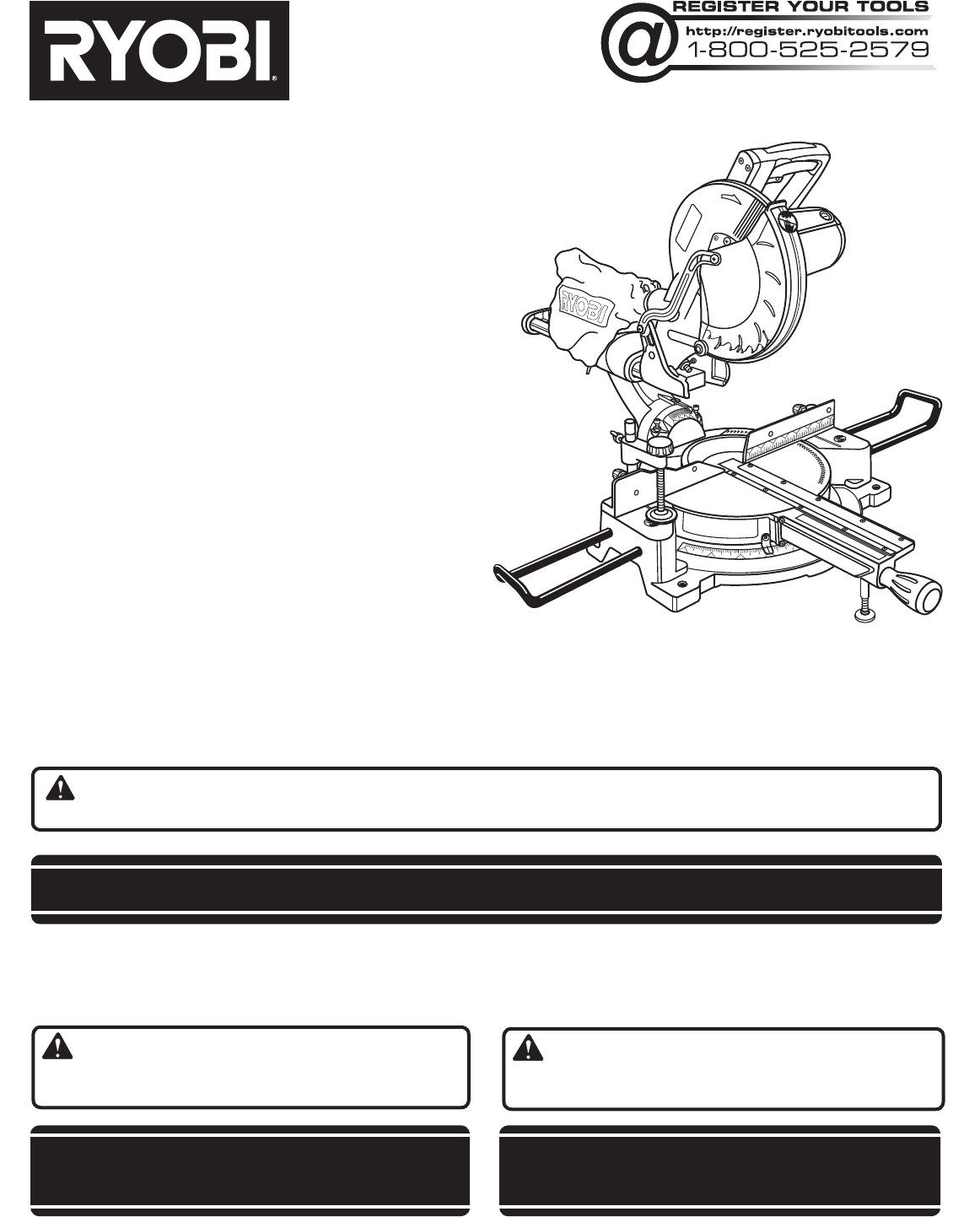
OPERATOR’S MANUALMANUEL D’UTILISATIONMANUAL DEL OPERADOR10 in. SLIDING COMPOUND MITER SAW WITH LASERDE 254 mm (10 po) SCIE À ONGLETS COMBINÉS COULISS
10 — EnglishFEATURESKNOW YOUR COMPOUND MITER SAWSee Figures 1 and 2.The safe use of this product requires an understanding of the information on the t
9900006298-7-13 (REV: 01)OPERATOR’S MANUAL / MANUEL D’UTILISATION /MANUAL DEL OPERADOR 10 in. SLIDING COMPOUND MITER SAW WITH LASERDE 254 mm (10 po) S
11 — EnglishFEATURESThe following tools (not included) are needed for making adjustments or installing the blade:TOOLS NEEDEDFig. 6COMBINATION SQUAREF
12 — EnglishLOOSE PARTS LISTFig. 7WARNING:The use of attachments or accessories not listed might be hazardous and could cause serious personal injury.
13 — EnglishASSEMBLYTRACE HOLES AT THESE LOCATIONS FOR HOLE PATTERNFig. 8MOUNTING SURFACESAW BASETRACE HOLES AT THESE LOCATIONS FOR HOLE PATTERNWARN
14 — EnglishASSEMBLYNOTE: Many of the illustrations in this manual show only portions of the compound miter saw. This is intentional so that we can cl
15 — EnglishASSEMBLYWORK CLAMP See Figure 11.WARNING:In some operations, the work clamp assembly may interfere with the operation of the blade guard
16 — EnglishASSEMBLYTO INSTALL / REPLACE THE BLADESee Figures 14 - 15.WARNING:A 10 in. blade is the maximum blade capacity of the saw. Never use a bla
17 — EnglishASSEMBLYWARNING:Make sure the spindle lock button is not engaged before reconnecting saw into power source. Never engage spindle lock bu
18 — EnglishASSEMBLYREMOVING / REPLACING THE THROAT PLATESee Figure 17.WARNING:The throat plate must be below the saw table. If the throat plate is to
19 — EnglishASSEMBLYSQUARING THE BLADE TO THE FENCESee Figures 18 - 21. Unplug the saw. Pull the saw arm all the way down and engage the lock pin
2 — English Introduction ...
20 — EnglishMITER TABLECOMBINATION SQUAREBLADEMITER FENCEASSEMBLYSCALE INDICATORFig. 22INDICATOR SCREWBEVEL SCALESQUARING THE BLADE TO THE MITER TABLE
21 — EnglishOPERATIONWARNING:Do not allow familiarity with tools to make you care-less. Remember that a careless fraction of a second is sufficient to
22 — EnglishOPERATIONTO MAKE NON-SLIDING CUTSWARNING:Securely tighten the slide lock knob when making any non-sliding cuts. Failure to tighten the kno
23 — EnglishFig. 28INDICATOR POINTOPERATIONTO BEVEL CUTSee Figures 28 - 29.A bevel cut is made by cutting across the grain of the workpiece with the b
24 — EnglishOPERATIONTO COMPOUND MITER CUTSee Figures 30 - 31.A compound miter cut is a cut made using a miter angle and a bevel angle at the same tim
25 — English00OPERATIONTO SUPPORT LONG WORKPIECESSee Figure 32.Long workpieces need extra supports. Supports should be placed along the workpiece so i
26 — EnglishOPERATIONWARNING:Never make a cut by pulling the saw toward you as the blade can climb on top of the workpiece and come toward you. Failur
27 — EnglishOPERATIONMAKING AN AUXILIARY FENCESee Figure 35.Certain unusual cuts may benefit from a thicker miter fence (auxiliary fence) due to the s
28 — EnglishOPERATION4 PITCH OF SIDENUMBER OF SIDES0°6M- 45.00°B- 0.00°5°10°15°20°25°30°35°40°45°50°55°60°65°70°75°80°85°90°578 910M- 36.00°B-
29 — EnglishOPERATIONFig. 36When cutting crown molding by this method, the bevel angle should be set at 33.85°. The miter angle should be set at 31.6°
3 — EnglishGENERAL SAFETY RULESWARNING: Read and understand all instructions. Failure to follow all instructions listed below, may result in electric
30 — EnglishOPERATIONWRONGWARNING: To avoid a kickback and to avoid serious personal injury, never position the concave edge of bowed or warped materi
31 — EnglishADJUSTMENTSWARNING:Before performing any adjustment, make sure the tool is unplugged from the power supply. Failure to heed this warning c
32 — EnglishADJUSTMENTSTRAVEL PIVOT ADJUSTMENT The saw arm should rise completely to the up position by itself. If the saw arm does not raise by i
33 — EnglishMAINTENANCEWARNING:When servicing, use only identical replacement parts. Use of any other parts may create a hazard or cause product damag
2 — Français Introduction ...
3 — FrançaisRÈGLES DE SÉCURITÉ GÉNÉRALESAVERTISSEMENT : Lire et veiller à bien comprendre toutes les instructions. Le non respect de toutes les instru
4 — FrançaisRÈGLES DE SÉCURITÉ GÉNÉRALES PORTER UNE PROTECTION AUDITIVE. Porter une protection auditive durant les périodes d’utilisation prolongée.
5 — Français S’ASSURER QUE LA LAME NE TOUCHE PAS LA PIÈCE. Ne jamais mettre la scie en marche si la lame touche la pièce à couper. Toujours laisser
6 — FrançaisSYMBOLESCertains des symboles ci-dessous peuvent être utilisés sur l’outil. Veiller à les étudier et à apprendre leur signification. Une i
7 — FrançaisCARACTÉRISTIQUES ÉLECTRIQUESCORDONS PROLONGATEURSLors de l’utilisation d’un outil électrique à grande distance d’une prise secteur, veille
4 — EnglishGENERAL SAFETY RULES NEVER USE IN AN EXPLOSIVE ATMOSPHERE. Normal sparking of the motor could ignite fumes. INSPECT TOOL CORDS PERIODIC
8 — FrançaisGLOSSAIRECoupes non traversantesToute coupe avec laquelle la lame ne traverse pas complètement la pièce.Blocs poussoirs (pour dégauchisseu
9 — FrançaisCARACTÉRISTIQUESFICHE TECHNIQUEAxe de lame ... 16 mm (5/8 po)Diamètre de la lame ...
10 — FrançaisCARACTÉRISTIQUESAPPRENDRE À CONNAÎTRE LA SCIE À ONGLETS COMPOSÉSVoir les figures 1 et 2.L’utilisation sûre de ce produit exige une compré
11 — FrançaisCARACTÉRISTIQUESBOUTON DE VERROUILLAGE DE BROCHEVoir la figure 4.Le bouton de verrouillage de broche verrouille la broche en empéchant la
12 — FrançaisLISTE DES PIÈCES DÉTACHÉESFig. 7AVERTISSEMENT :L’utilisation de pièces et accessoires non listés peut être dangereux et entraîner des ble
13 — FrançaisASSEMBLAGETRACER DES TROUS À CES EMPLACEMENTS SELON LE GABARIT DE TROUSSURFACE DE FIXATIONBASE DE LA SCIETRACER DES TROUS À CES EMPLACEME
14 — FrançaisASSEMBLAGENOTE : De nombreuses illustrations de ce manuel ne montrent que des parties de la scie à onglets composés. Cette présentation
15 — FrançaisASSEMBLAGEBRIDE DE SERRAGE DE PIÈCEVoir la figure 11.AVERTISSEMENT :Dans certaines conditions, la bride de serrage de pièce peut perturbe
16 — FrançaisINSTALLATION / REMPLACEMENT DE LA LAMEVoir les figures 14 et 15.AVERTISSEMENT :La taille maximum de lame pouvant être utilisée sur cette
17 — FrançaisASSEMBLAGEAVERTISSEMENT :S’assurer que le bouton de verrouillage de la broche n’est pas engagé avant de brancher la scie sur la source d’
5 — English NEVER PERFORM ANY OPERATION FREEHAND. Always place the workpiece to be cut on the miter table and position it firmly against the fence a
18 — FrançaisASSEMBLAGERETRAIT / REMPLACEMENT DE LA PLAQUE À GORGEVoir la figure 17.ATTENTION : La plaque à gorge doit être au dessous de la table de
19 — FrançaisGUIDE D’ONGLETASSEMBLAGEÉQUERRAGE DE LA LAME PAR RAPPORT AU GUIDEVoir les figures 18 à 21. Débrancher la scie. Abaisser complètement
20 — FrançaisASSEMBLAGEINDICATEUR D’ÉCHELLERAPPORTEUR D’ANGLEÉQUERRAGE DE LA LAME PAR RAPPORT À LA TABLE À ONGLETSVoir les figures 22 à 25. Débranch
21 — FrançaisUTILISATIONAVERTISSEMENT :Ne pas laisser la familiarité avec l’outil faire oublier la prudence. Ne pas oublier qu’une fraction de seconde
22 — FrançaisUTILISATIONPOUR RÉALISER DES COUPES NON COULISSANTESAVERTISSEMENT :Bien serrer le bouton de verrouillage du coulissement lors de coupes n
23 — FrançaisVIS D’INDICATEURINDICATEUR D’ÉCHELLEUTILISATIONCOUPE EN BISEAUVoir les figures 28 et 29.Une coupe en biseau est réalisée en travers du gr
24 — FrançaisUTILISATIONCOUPE D’ONGLET COMPOSÉVoir les figures 30 et 31.Une coupe d’onglet composé consiste à utiliser un angle d’onglet et un angle d
25 — FrançaisUTILISATIONSUPPORT DE PIÈCES LONGUESVoir la figure 32.Les pièces longues nécessitent un support additionnel. Les supports doivent être pl
26 — FrançaisUTILISATION AVERTISSEMENT :Ne jamais couper en tirant la scie vers soi car la lame pourrait grimper sur le haut de la pièce et se déplace
27 — FrançaisCOMMENT FABRIQUER UNE GUIDE AUXILIAIREVoir la figure 35.Certaines coupes inhabituelles peuvent être facilitées par un guide d’onglet plu
6 — EnglishSYMBOLSSome of the following symbols may be used on this tool. Please study them and learn their meaning. Proper interpretation of these s
28 — FrançaisUTILISATION4 ANGLE DE CÔTÉNOMBRE DE CÔTÉS0°65°10°15°20°25°30°35°40°45°50°55°60°65°70°75°80°85°90°578 910Chaque angle B (biseau) et O (ong
29 — FrançaisUTILISATIONFig. 36Lors de la coupe d’une moulure couronnée à l’aide de cette méthode, l’angle de biseau doit être réglé à 33,85°. L’angle
30 — FrançaisUTILISATIONINCORRECTAVERTISSEMENT : Pour éviter les risques de rebond et de blessures graves, ne jamais placer le bord concave d’une pièc
31 — FrançaisRÉGLAGESAVERTISSEMENT :Avant d’effectuer tout réglage, s’assurer que l’outil est débranché. Le non respect de cet avertissement pourrait
32 — FrançaisRÉGLAGESRÉGLAGE DU PIVOT DE BRAS Le bras de la scie doit se relever complètement de lui-même. Si le bras de la scie ne se relève pas
33 — FrançaisENTRETIENAVERTISSEMENT :Utiliser exclusivement des pièces identiques à celles d’origine pour les réparations. L’usage de toute autre pièc
34 — FrançaisNOTES
2 — Español Introducción ...
3 — EspañolREGLAS DE SEGURIDAD GENERALESADVERTENCIA: Lea y comprenda todas las instrucciones. El incumplimiento de las instrucciones señaladas abajo p
4 — EspañolREGLAS DE SEGURIDAD GENERALESMANTENGA LAS HOJAS DE CORTE LIMPIAS Y AFILADAS. Las hojas de corte afiladas reducen al mínimo los paros y l
7 — EnglishELECTRICALEXTENSION CORDSWhen using a power tool at a considerable distance from a power source, be sure to use an extension cord that has
5 — Español NUNCA UTILICE UN TOPE DE LONGITUD EN EL EXTREMO DE DESPERDICIOS SUELTOS DE UNA PIEZA DE TRABAJO SUJETA CON PRENSA. NUNCA sujete o dob
6 — EspañolSÍMBOLOSEs posible que se empleen en esta herramienta algunos de los siguientes símbolos. Le suplicamos estudiarlos y aprender su signific
7 — EspañolASPECTOS ELÉCTRICOSDOBLE AISLAMIENTOEl doble aislamiento es una característica de seguridad de las herramientas eléctricas, la cual elimina
8 — EspañolGLOSARIO DE TÉRMINOSCortes sin traspasoEs cualquier operación de corte en la cual la hoja de corte no traspasa completamente el espesor de
9 — EspañolCARACTERÍSTICASESPECIFICACIONES DEL PRODUCTOÁrbol de la hoja de corte ... 16 mm (5/8 pulg.)Diámetro de la hoj
10 — EspañolCARACTERÍSTICASFAMILIARÍCESE CON LA SIERRA INGLETEA-DORA COMBINADAVea las figuras 1 y 2.El uso seguro que este producto requiere la compr
11 — EspañolCARACTERÍSTICASGUÍA DE INGLETESLa guía de ingletes de la sierra ingleteadora combinada se suministra para apoyar firmemente la pieza de tr
12 — EspañolLISTA DE PIEZAS SUELTASFig. 7ADVERTENCIA:El empleo de aditamentos o accesorios no enumerados arriba podría ser peligros y causar lesiones
13 — EspañolARMADOSEÑALE EL CENTRO DE LOS AGUJEROS EN ESTOS LUGARESSUPERFICIE DE MONTAJEBASE DE LA SIERRASEÑALE EL CENTRO DE LOS AGUJEROS EN ESTOS LUG
14 — EspañolARMADONOTA: En muchas de las ilustraciones de este manual se muestran sólo porciones de la sierra ingleteadora compu-esta. Se hace así del
8 — EnglishGLOSSARY OF TERMSNon-Through CutsAny cutting operation where the blade does not extend completely through the thickness of the workpiece.Pu
15 — EspañolARMADOPRENSA DE TRABAJOVea la figura 11.ADVERTENCIA:En algunas operaciones el conjunto de la prensa de trabajo puede interferir en el movi
16 — EspañolARMADOPROTECCIÓN INFERIOR DE LA HOJAPARTE(S) PLANA(S) DEL HUSILLOTAPA DEL PERNO DE LA HOJAARANDELA INTERIOR DE LA HOJA CON DOS PARTES PLAN
17 — EspañolARMADOADVERTENCIA:Asegúrese de que el botón del seguro del husillo no esté oprimido antes de volver a conectar la sierra al suministro de
18 — EspañolARMADOEXTRACCIÓN / REEMPLAZO DE LA PLACA DE GARGANTAVea la figura 17.ADVERTENCIA:La placa de la garganta debe estar a debajo de la mesa d
19 — EspañolARMADOESCUADRADO DE LA HOJA CON LA GUÍAVea las figuras 18 a 21. Desconecte la sierra. Tire del brazo de la sierra completamente hacia
20 — EspañolARMADOINDICADOR DE LA ESCALAESCALA DE INGLETESTORNILLO DEL INDICADORESCUADRADO DE LA HOJA CON LA MESA DE INGLETESVea las figuras 22 a 25
21 — EspañolFUNCIONAMIENTOADVERTENCIA:No permita que su familarización con las herramientas lo vuelva descuidado. Tenga presente que un descuido de un
22 — EspañolFUNCIONAMIENTOPARA REALIZAR CORTES NO DESLIZANTESADVERTENCIA:Apriete firmemente la perilla de fijación de la guía telescópica para realiz
23 — EspañolFUNCIONAMIENTOPARA CORTAR A BISELVea las figuras 28 y 29.Un corte en bisel se efectúa cortando a través de la fibra de la pieza de trabajo
24 — EspañolFUNCIONAMIENTOPARA EFECTUAR UN CORTE A INGLETE COMBINADOVea las figurad 30 y 31.Un corte en bisel combinado es un corte efectuado a un áng
9 — EnglishFEATURESFig. 1 and 2PRODUCT SPECIFICATIONSBlade Arbor ... 5/8 in.Blade Diameter
25 — EspañolFUNCIONAMIENTOPARA APOYAR LAS PIEZAS DE TRABAJO LARGASVea la figura 32.Las piezas de trabajo largas necesitan soportes extra. Los soportes
26 — EspañolFUNCIONAMIENTO ADVERTENCIA:Nunca realice cortes tirando de la sierra hacia usted, ya que esto podría hacer que la hoja se montara sobre la
27 — EspañolFUNCIONAMIENTOFORMA DE HACER UNA GUÍA AUXILIARVea la figura 35.Puede ser útil el uso de una guía de ingletes de mayor grosor (guía auxilia
28 — EspañolFUNCIONAMIENTOCada cantidad, B (bisel) y M (inglete), se da con una tolerancia de 0,005°.AJUSTES DE ÁNGULOS COMBINADOS PARA ESTRUCTURAS CO
29 — EspañolFUNCIONAMIENTOFig. 36Al cortar molduras de corona con este método, el ángulo de bisel debe fijarse a 33,85°. El ángulo de inglete debe fij
30 — EspañolFUNCIONAMIENTOFORMA INCORRECTAADVERTENCIA: Para evitar un contragolpe y posibles lesiones graves, nunca coloque el canto cóncavo de un mat
31 — EspañolAJUSTESADVERTENCIA:Antes de efectuar cualquier ajuste, asegúrese de que la herramienta esté desconectada del suministro de corriente. La i
32 — EspañolAJUSTESAJUSTES DE LOS TOPESVea la figura 42.NOTA: Estos ajustes se realizaron en la fábrica y normalmente no requieren reajustarse.Para aj
33 — EspañolMANTENIMIENTOADVERTENCIA:Al dar servicio a la unidad, sólo utilice piezas de repuesto idénticas. El empleo de piezas diferentes puede caus
34 — EspañolNOTES / NOTAS
Produits connexes et manuels pour Scies à moteur Ryobi TSS100L1
 (30 pages)
 (30 pages)
 (32 pages)
© 2020, manymanuals.fr. Tous droits réservés | 0.493 s |
 Manymanuals.com
 Manymanuals.de
 Manymanuals.fr
 Manymanuals.it
 Manymanuals.pl
 Manymanuals.cz
 Manymanuals.es
 Manymanuals-pt.com
Commentaires sur ces manuels